Posts Tagged ‘Serial Interface’

h1

USB Power Delivery Showcase from INTEL

July 11, 2013

At the Technology Showcase at IDF Beijing, INTEL demonstrated a typical application of the USB Power Delivery feature: a portable PC delivering through a USB2.0 connection video streaming at 480Mbit/s (not really a big deal) and at the same time the power to supply a LCD monitor.

INTEL DEMO@IDF

Read the rest of this entry ?

h1

Developing a USB Power Delivery device? Let’s talk about solutions!

July 1, 2013

Are you thinking to develop or evaluate an USB-PD device? If yes, I’m sure the first problem you are facing is the unavailability of USB-PD semiconductor solutions to build your concept board and of USB-PD enabled products to be used as peer for your system (at least at this date). This is for sure a major issue to assess the system requirements and to evaluate the performances. The possibility to have a USB-PD evaluation board permits the engineering team to start playing with this new protocol, to build the system and to start the implementation and debug of the high level functionalities.

Up to date two solutions are available in the market: one coming from Obsidian Technology and one from Canova Tech.

Everything I know about Obsidian can be found in the website. They came as first in the market with an USB-PD solution and they are offering an USB-PD development board  (OTS9102) based on a proprietary IC (OTI9121) implementing the physical layer (PHY).

CT20600

More I can say about Canova Tech (sorry, it’s the company I’m working for!). It’s currently developing an USB-PD PHY block, the CT20600.

The CT20600 is a USB-PD compliant PHY IP implementing all the features described in the current USB-PD specifications. The block can be integrated in a more complex power management unit (see previous post) or in standalone device for cost sensitive applications. The CT20600 can be ported to most of the analog CMOS processes available in the market.

CT20600 DVLP Board 1V1

A development board has been developed in order to assess the architecture and to implement the digital blocks of the PHY and the upper layers, like the protocol layer. Waiting for the incoming silicon samples, at the moment the board v1.1 implements the analog parts of the USB-PD PHY using discrete components and the digital blocks in a FPGA.

A detailed description of this board will follow soon.

Any comment and feedback is welcome.
Stay tuned.

h1

USB Power Delivery on Battery Operated Devices [Group 1]

June 19, 2013

A previous post proposed a possible categorization of all the devices potentially involved on the new incoming  USB Power Delivery:

  1. Battery operated and complex devices, like smartphones, tablets, portable PCs, cameras
  2. USB peripherals, like external hard disks, printers or usb
  3. No-USB peripherals with <100W power consumption like monitors, toys and gadgets
  4. Power supply devices like wall chargers, power bricks.

Each category has different needs, requirements and constraints and it’s logic to foreseen for the USB-PD different possible implementations and implications in the system architecture.

Let’s start with the 1st category, the most complex.

Battery Operated Devices

This category includes all the devices with a battery as primary power source and with a USB port used for secondary energy source for battery recharge. This is clearly the most complex device, as it can play as an energy consumer (during internal battery recharge) or as an energy provider (in case, for example, of supplying an external hard disk). I’m clearly referring to Tablets, smartphones and portable PCs. They have already complex power policies and strategies and one or more USB ports for data communication. So not a big issue to integrate a USB-PD feature in such devices. Quite easy from a mechanical point of view, but it’s worth to discuss deeper the possible electronic implementations.

Read the rest of this entry ?

h1

USB Power Delivery – A System Point of View

May 18, 2013

The emerging USB Power delivery standard opens new and exciting scenarios in the consumer market. It will change the way we are dealing daily with our portable devices. We will charge much faster our tablet, smartphone or supply our portable PC or USB interfaces without any secondary energy source. All with a standard connector, as the European Union is requiring. Our life is going to be simplified!CHARGER_CONNECTORS

This welcome and long waited feature will have anyhow a deep impact in the architecture of the power manager of each device, like  battery operated devices, tablet, smartphone, USB peripherals, monitors and chargers. And more important, each device in this scenario requires dedicated approaches and implementations with different level of integration.

Read the rest of this entry ?

h1

HowTo qualify an USB Power Delivery PHY

April 23, 2013

As far as I know, no USB Power Delivery products are available on the market and no standard or ASSP ICs can be found yet. Most  probably the major semiconductor companies are hard working to deliver soon solutions for this new standard and fabless semiconductor companies are ready to offer dedicated IP (e.g. CT20660 from Canova Tech).

USB EYEAs any USB product, compliance and interoperability tests should be performed in order to grant the requested level of compatibility with any compliant solution. The USB-IF defines a Compliance Program that provides reasonable measures of acceptability. Products that pass this level of acceptability are added to the Integrators List. You can check the  USB-IF Compliance Updates webpage for any news and update.

Two ways are available to have your product in this Integration List:

  1. participating in the USB-IF Sponsored Compliance Workshops
  2. contacting one of the Independent Test Labs.

Please check the USB.org website for more information.

Before submitting your products to compliance tests, it’s important and warmly encouraged by the USB-IF itself to run internally tests procedure to validate the solution. Normally the USB-IF delivers for any USB standard a list of test procedures and a test setup description to validate your design and debug it with a standard set of tests. This is very important and really crucial for new designs, especially in the case of a new USB standard without available alternative solutions to make comparisons and interoperability tests.

Unfortunately, up to day the USB-IF did not release yet the test procedures for the USB-PD delivery and there is no date for the delivery of such documentation.  See below the extract on the USB Power delivery page:

Compliance testing for products conforming to the Power Delivery Specification and the related Power Delivery icons are currently under development. More details to be added here later.”

Well, the USB-PD icon delivering is less important. Agreed.

I will continuously check the USB-IF webpage for any news and and I’m constantly  looking for any alternative and viable way to perform in-house preliminary compliance tests.

Keep tuned.

h1

Interview with S.Carlsen, commitee member for USB Power Delivery standardization

April 3, 2013

After my recent posts (USB-PD IntroPHYProtocol Layer) about USB Power Delivery, I had the chance to come in touch with great people and I started with them interesting and promising discussions. In the early phases of any new emerging technology it’s always important to build a wide network of  interest, competences and contributions.

Charger

In this sense, it is a pleasure to introduce Sten Carlsen, a member of the standardization committee of the USB-PD. Having covered this active role, Sten can help to better understand the new standard and read it out of the specification. Below the interview I had with him.

Read the rest of this entry ?

h1

USB-PD: Protocol Layer explained

March 27, 2013

After my previous post regarding the Power Delivery PHY, it’s now time to introduce the Protocol Layer (PL).USB-PD Stack PL

The PL communicates with the lower PHY layer and with the upper Policy Engine and it is responsible to form the messages used to communicate information between a pair of USB-PD ports.

It receives inputs from the Policy Engine indicating which messages to send and indicates the responses back to the Policy Engine. But it is responsible to  form Capabilities messages, requests and acknowledgements and ping packets. It implements counters for packet numbering and dedicated timer for timeouts.

The basic protocol uses a push model where the Provider pushes it capabilities to the Consumer that in turn responds with a request based on the offering. However, the Consumer may asynchronously request the Provider’s present capabilities and may select another voltage/current.

The PL architecture is based on timers, state machines and counters, see the picture, and it’s a pure digital implementation. Below a brief description of each block.

UBS-PD PL

Read the rest of this entry ?

h1

USB Power Delivery: PHY explained

March 14, 2013

USB-PD icons
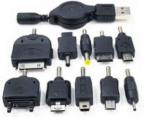
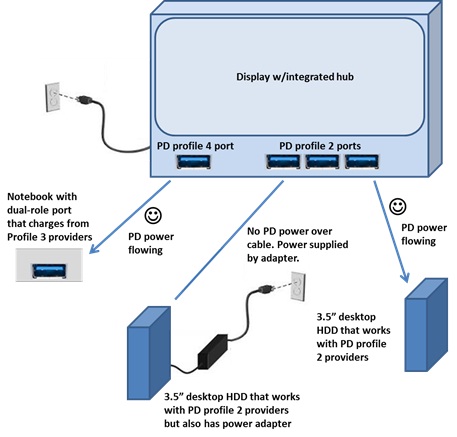
The new USB Power Delivery standard (USB-PD) will enable devices to deliver or sink power  over USB cable up to 100W in 6 power profiles.  And hopefully it will simplify our life, currently busy with power adapters, battery chargers and connectors. In a previous post of mine, the main features of the USB-PD have been presented.

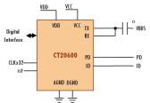
The USB-PD defines a protocol that enable the producer and the consumer device to negotiate the power capabilities and to tailor dinamically the actual power needs. To be compatible with the classic standard USB2.0 and USB3.0, this communication protocol has been specified as a powerline communication (PLC) over VBUS, as depicted in a simplified architecture below. In this configuration the USB-PD PHY in not interfering with the standard communication bus of a USB port and in principle nothing is preventing to have a separate and standalone USB-PD device.
usb-pd architecture

The USB-PD communication protocol is an half-duplex, FSK modulated channel. The frequency carrier is 23.2MHz and the FSK frequency deviation 500KHz. The bit rate is 300 Kbps.

The USB-PD PHY interfaces the VBUS wire only. An inductor is required to isolate the transceiver and the channel from the noisy power supply or load.

The USB-PD standard Specification doesn’t enter in implementation details, but I believe the most probable implementation will use an AC coupling with the VBUS, as depicted above. This approach permits to use low voltage silicon voltage processes, as the capacitor blocks the DC component of the VBUS that can be as high as 20V nominal.

In the above architecture, no mention of the standard USB interface, that it completely separated and independent. It will be interesting to investigate in another post how to protect the VBUS input in case of USB-PD functionality.

USB-PD PHY (TX)

The TX block receives data to be sent from the upper layer (protocol layer). The functions to be implemented are:
  1. Receive incoming data from upper layer
  2. Append the calculated CRC
  3. 4b5b encode to avoid DC component in the data stream
  4. Insert  preamble and packet delimiters
  5. FSK Modulator
  6. VUSB Drive with a bandpass filter

usb-pd tx

Without enter in implementation details, part of the TX block involves pure digital design. It will be interesting to investigate the implementation of the FSK modulator. The 4b5b encoder avoids DC component in the data stream. The  preamble makes the clock synchronization easier and the packet delimiters make the packet sync easier at the RX side.

USB-PD PHY RX

The RX block should receive data on the VBUS and send the payload data to the upper layer (protocol layer). The functions to be implemented are:
  1. PassBand Filter
  2. Squelch Detector
  3. FSK Demodulator
  4. Extract payload
  5. 4b5b Decoder
  6. CRC check
  7. Data to upper layer

usb-pd rx

The most interesting part of the RX is the FSK demodulator, as there are many alternative implementations. A coming post will be dedicated to this topic.

The RX squelch detector is requested to minimize the power consumption of the RX block when no data communication on VBUS. The CRC calculation and validation permits to discharge corrupted packets. Only bit-wise correct packet will be delivered to the upper layer (protocol layer).

h1

Ready for USB Power Delivery?

March 12, 2013

The USB promoter groups released on July 2012 the new Power Delivery 1.0 specifications for USB3.0 and USB2.0. This new profile defines the mechanisms to deliver flexible and higher power over  a standard USB data channel. USB Power Delivery (PD) devices can now delivery up to 100W and implement  power management strategies across multiple peripherals by allowing each device to take only the power it requires, and to get more power when required for a given application.

USB-PD icons

Compatible with the actual mechanical (cables and plugs) and protocol ecosystem and in addition to the current BC1.2 specifications(USB Battery Charge v1.2),  the new PD defines new cables and plug/sockets able to manage this higher power. The PD negotiation between devices is performed by a new specific communication protocol over the VBUS one-wire channel, without interfering with the USB data channel.

USB-PD Profiles

Compared with Thunderbolt, that is offering higher data speed performances, the USB PD specify a power delivery ten times what Thunderbolt can do. It means that you can charge up your laptop or power most any peripheral via Universal Serial Bus.
The natural implementation of this new PD profile is the wall plug charger that can now be used to deliver after negotiation enough power to supply and charge notebooks and portable devices. But any USB device with enough power capabilities, like a PD-enabled monitor, can be the USB power hub for multiple external devices like HDD/SDDs and notebook, as in picture below.

USB-PD Ecosystem

The new USB PD profile is a promising effort to unify and standardize the common needs of power delivery and to simplify the number and typologies of power cables we are now managing to charge and supply our battery operated devices.